

1. 서 론
2. 헬리컬 파일의 지지력 산정방법
2.1 Individual bearing method
2.2 Cylindrical shear method
2.3 Torque correlation method
3. Individual bearing method와 Cylindrical shear method의 비교
4. Application of torque correlation method
5. 결 론
1. 서 론
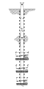
헬리컬 파일(Helical Pile)은 중공형 축에 축보다 큰 직경을 갖는 나선형 원판이 부착되어 있는 형상으로, 지지력을 발현하는데 있어 축의 주면마찰력 이외에 각기의 나선형 원판이 선단지지력을 발휘할 수 있다(Livneh and Naggar, 2008). 현재 헬리컬 파일의 지지력 예측에 사용되고 있는 산정법으로는 Individual bearing method, Cylindrical shear method, Torque correlation method가 널리 사용되고 있다(Perko, 2009). Individual bearing method는 축에 부착된 나선형 원판 각각이 선단지지력을 발현하여 헬리컬 파일의 지지력을 각 원판의 선단지지력과 축의 주면마찰력의 합으로 산정하는 방법이며, Terzaghi(1943)의 제안식이나 Meyerhof(1951)의 제안식을 사용하고 있다. Cylindrical shear method는 나선형 원판 사이의 지반 전체가 동일하게 저항하여, 원판 사이의 지반에 원통형으로 전단력이 발생하는 것을 가정하여 지지력을 산정하는 방법이다(Mooney et al., 1985). 따라서 Cylindrical shear method에서는 헬리컬 파일의 지지력을 최하단 원판의 선단지지력과 원통형 지반의 전단력, 그리고 축의 주면마찰력의 합으로 산정하고 있다. Individual bearing method와 Cylindrical shear method의 개념도를 Fig. 1에 나타내었다.
|
|
(a) Individual bearing method | (b) Cylindrical shear method |
Fig. 1. Schematics of individual bearing and cylindrical shear methods (Perko, 2009) | |
orque correlation method는 현장에서 측정되는 토크값을 지지력 예측에 사용하는 경험적인 방법으로, Hoyt and Clemence(1989)에 의해 시공시의 최종토크와 지지력의 상관관계가 정립되었다. Hoyt and Clemence(1989)는 세 가지 방법을 다양한 시공 사례를 통해 측정 지지력과 예측 지지력을 비교 분석하였다. 분석결과 Torque correlation method의 신뢰성이 가장 높다고 판단하였으나, 각 산정방법은 헬리컬 파일이 시공된 지반조건에 따라 지지력 값의 편차가 상대적으로 크게 발생하기 때문에 어느 한 가지 방법만을 사용하여 현장 시공된 헬리컬 파일의 지지력을 예측하는 것에는 어려움이 따른다. 국내에서는 현장 시공된 헬리컬 파일의 지지력을 예측하고 비교한 사례가 있다(Ha et al., 2013). 본 연구에서는 세 가지 지지력 예측 방법의 국내 지반에의 적용 신뢰성을 판단하기 위해 연계논문인 Lee et al. (2014)에서 제시한 측정 지지력과 세 가지 방법에 의한 예측 지지력을 비교분석하여 지지력 예측방법에 대한 적용성을 검토하였다.
2. 헬리컬 파일의 지지력 산정방법
2.1 Individual bearing method
Individual bearing method는 Fig. 1(a)와 같이 각각의 원판에 하중이 분포하여 선단지지력을 발현하여 헬리컬 파일의 지지력을 각 원판의 선단지지력과 축의 주면마찰력의 합으로 산정하는 방법으로 식 (1)과 같다.
 (1)
(1)
여기서,  : 개별 극한지지응력
 : n번째 나선형 원판의 면적
 : 지반과 축 사이의 부착력
 : 최상부 나선형 원판까지의 축 길이
 : 축의 직경
일반적으로 선단의 극한지지응력은 Terzaghi(1943)의 제안식이나 Meyerhof(1951)의 제안식을 사용하며, Terzaghi의 제안식을 수정한 Meyerhof의 제안식이 보편적으로 사용되고 있다. Meyerhof의 제안식을 사용하여 각 원판의 선단 지지력을 산정하기 위한 개별 극한지지응력의 산정방법은 식 (2)와 같다.
 (2)
(2)
여기서, c : 점착력 : 유효응력
 : 기초의 길이와 폭(원판 직경으로 동일)
 : 지반의 단위중량
 : 지지력계수
 : 형상계수
 : 심도계수
식 (2)에 사용된 지지력계수와 형상계수, 심도계수는 각각 식 (3)에 나타내었다.
 (3)
(3)


여기서,  : 지반의 내부마찰각
Perko(2009)는 점토지반에서의 47개의 시공사례에서 실측 지지력과 Individual bearing method를 사용하여 예측한 지지력의 비율은 평균적으로 1.03이며(표준편차 0.47), 모래지반에서의 54개의 시공사례에서는 1.16(표준편차 0.84)임을 기술하였다.
2.2 Cylindrical shear method
Cylindrical shear method는 Fig. 1(b)와 같이 원판 사이의 지반 전체가 동일하게 저항한다고 가정하여 지지력을 산정하는 방법이다. 따라서 지지력은 최하단 원판의 선단지지력, 원통형 지반의 전단력, 그리고 축의 주면마찰력의 합으로 식 (4)와 같이 산정할 수 있다.
 (4)
(4)
여기서,  : 최하부 나선형 원판의 면적
 : 원통형 지반의 전단강도
 : 나선형 원판 사이에 형성된 원통형 지반의 길이
Perko(2009)는 점토지반에서의 32개의 시공사례에서 실측 지지력과 Cylindrical shear method로 예측한 지지력의 비율의 평균을 0.82(표준편차 0.26), 모래지반에서 42개의 시험결과를 바탕으로 산정된 평균값은 1.07(표준편차 0.58)임을 기술하였으며, 일반적으로 Individual bearing method와 Cylindrical shear method를 통해 산정한 지지력 예측값 중에서 작은 값을 사용하는 것이 적절하다고 제시하였다.
2.3 Torque correlation method
Torque correlation method은 현장에서 측정할 수 있는 시공 장비의 최종토크를 측정하여 지지력-토크 계수를 이용하여 간편하게 지지력을 예측하는 경험적인 방법이다(Deardorff, 2007). Hoyt and Clemence(1989)는 Individual bearing method과 Cylindrical shear method, 그리고 기존에 경험적으로 사용되던 토크와 지지력의 관계에 대해 실측지지력과 예측지지력을 비교 분석하였다. Torque correlation method은 시공 시의 최종토크로부터 지지력을 예측하는 방법으로 관계식은 식 (5)와 같다.
 (5)
(5)
여기서,  : 지지력-토크 상수 (
 )
)
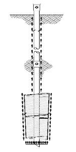
Hoyt and Clemence(1989)는 세 가지 방법 중에서 상대적으로 Torque correlation method가 실측 지지력과 예측 지지력의 차이가 적다고 언급했으며, Perko(2009)는 141개의 현장시험을 바탕으로 축의 직경과 지지력-토크 상수의 관계를 나타내었으며(Fig. 2 참조), 이를 Table 1에 정리하였다. 국내에서도 Torque correlation method가 상대적으로 타당하다고 분석한 사례가 있다(Ha et al., 2013).
3. Individual bearing method와 Cylindrical shear method의 비교
본 논문에서는 연계논문(Lee et al., 2014)에서 현장 정재하시험을 통해 측정한 중소구경 헬리컬 파일의 지지력을 Individual bearing method과 Cylindrical shear method을 통해 산정한 예측 지지력과 비교하였다. 시험시공은 경기도 김포시 통진읍 일대에서 수행하였으며, 시공된 헬리컬 파일은 중소구경 범위인 73mm와 114mm 직경을 갖는 2종류의 축과 400, 350, 300, 250mm 직경의 원판 조합(1개 또는 3개)으로 구성되었다. 지지력 예측에 사용한 지반 물성치는 연계논문인 Lee et al.(2014)의 현장 지반 조사결과로 부터 산정된 내부마찰각 25°와 점착력 0.0(tf/m2)을 사용하였다.
| |
Fig. 2. Empirical capacity-to-torque ratio (Perko, 2009) | |
Table 1. Predicted | |
Shaft diameter (mm) |
(m-1) |
54 | 37 |
63 | 32 |
73 | 28 |
76 | 27 |
89 | 24 |
114 | 19 |
152 | 15 |
203 | 12 |
254 | 10 |
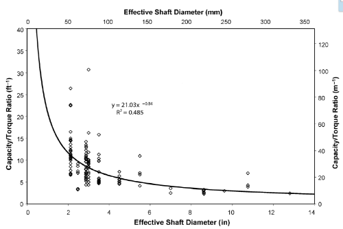
 values with shaft diameters (Perko, 2009)
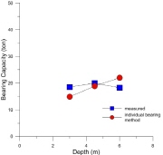
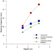
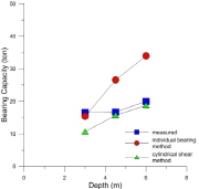
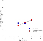
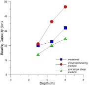
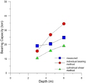
일반적으로 헬리컬 파일의 지지력은 원판의 선단지지력이 차지하는 비중이 상대적으로 매우 크다. 특히 상대적으로 심도가 낮은 경우에는 지지력의 대부분이 원판의 선단지지력으로 발현된다. 이러한 이유로 원판의 개수, 크기에 따라 산정되는 지지력을 비교하기 위하여 두 가지 축의 직경(73mm, 114mm) 중에서 먼저 축의 직경이 73mm이고 직경이 400 mm 원판 1개가 부착된 헬리컬 파일(TypeI)의 실측 및 예측 지지력을 Fig. 3(a)에, 직경이 각각 400, 350, 300mm인 3개의 원판이 부착된 헬리컬 파일(Type II)를 Fig. 3(b), 그리고 마지막으로 직경이 각각 350, 300, 250mm인 3개의 원판이 부착된 헬리컬 파일(TypeIII)를 Fig. 3(c)에 비교하였다. 1개의 원판이 부착된 헬리컬 파일(TypeI)의 지지력 예측은 Individual bearing method과 Cylindrical shear method에서 동일한 결과를 얻는다. Fig. 3(a)에서 Individual bearing method (또는 Cylindrical shear method)으로 예측한 지지력이 3m와 4.5m 심도에서는 실측 지지력에 비해 다소 작게 산정되었으나, 6m 지점에서는 실측보다 크게 산정되었다. 이는 6m지점에서 실측 지지력의 측정오차로 사료된다. Fig. 3(b)와 Fig. 3(c)에서 원판이 3개 부착된 헬리컬 파일(TypeII와 III)은 Individual bearing method으로 예측한 지지력의 경우 실측지지력보다 큰 값을 보여주었고, Cylindrical shear method의 경우 상대적으로 작은 값을 보였다. 또한 축의 직경이 114mm인 헬리컬 파일의 예측 및 실측 지지력의 비교를 Fig. 4에 나타내었다. Fig. 4(a)에서 원판이 1개 부착된 헬리컬 파일(TypeI)은 심도가 낮을 경우는 예측 지지력이 다소 과소평가 되고, 원판이 3개 부착된 헬리컬 파일(TypeII와 III)은 축의 직경이 73mm인 경우와 유사하게, Individual bearing method는 실측 지지력보다 큰 값을, Cylindrical shear method은 실측 지지력보다 작게 헬리컬 파일의 지지력을 예측한다. 즉, 실측된 헬리컬 파일의 지지력은 일반적으로 Individual bearing method로 산정한 상한값과 Cylindrical shear method로 예측한 하한값 사이에 위치함을 알 수 있다. 헬리컬 파일의 축의 직경, 원판의 형상에 따라 두 가지 방법으로 예측한 지지력과 실측 지지력 값을 Table 2에 나타냈다.
|
|
|
(a) TypeI | (b) TypeII | (c) TypeIII |
Fig. 3. Relation between measurement and prediction (shaft diameter 73 mm) | ||
4. Application of torque correlation method
Torque correlation method에 적용되는 지지력-토크 계수( )는 축의 직경에 영향을 받으며, Perko(2009)는 축 직경 73mm의 경우 28m-1, 114mm의 경우 19m-1을 제안하였다(Table 1 참조). 본 논문에서는 연계논문(Lee et al., 2014)에서 현장 측정을 통해 제시한 최종 관입토크를 Perko(2009)가 제안한
  값과 식 (5)을 이용하여 지지력을 예측하였다. 현장 정재하시험으로 측정된 헬리컬 파일의 지지력을 Torque correlation method로 예측한 지지력으로 정규한 값을 Table 3에 나타냈다. Table 3에서 축 직경이 114mm인 헬리컬 파일은 Perko(2009)가 제시한
  =19m-1를 적용한 예측 지지력이 실측값과 유사하나, 축 직경이 73mm인 헬리컬 파일은 Perko(2009)가 제시한
  =28m-1를 적용시, Torque correlation method이 지지력을 대략 2배 정도 과대평가 한다. 따라서, 축 직경이 73mm인 헬리컬 파일에 대해서도 축 직경 114mm에 적용한
  =19m-1를 적용하여 예측한 지지력을 실측 지지력과 비교하여 Table 3에 “Recommended”에 비교하였다. 최종토크와 지지력의 상관도를 선형회귀를 통해 분석한 결과, 다소 분산성을 보이나 전반적으로 선형비례하므로, Torque correlation method를 통하여 헬리컬 파일의 지지력을 예측할 때 지지력-토크 계수를 축의 직경에 관계없이 19m-1을 사용하는 것이 적합하다고 사료된다.


5. 결 론
본 연구에서는 국내 지반에 시공된 중소구경 헬리컬 파일의 지지력을 예측하는데 있어 적절한 지지력 산정 방법을 검토하기 위해 연계논문(Lee et al., 2014)의 현장 정재하시험에서 측정된 지지력과 3가지 방법으로 예측한 지지력을 비교 분석하였다.
(1)헬리컬 파일에 대한 현장 정재하시험 결과와 비교하여 Individual bearing method는 실측 지지력보다 크게, Cylindrical shear method은 실측 지지력보다 작게 지지력을 예측한다. 실측된 헬리컬 파일의 지지력은 일반적으로 Individual bearing method로 산정한 상한값과 Cylindrical shear method로 예측한 하한값 사이에 위치한다.
(2)Torque correlation method으로 예측한 지지력은 두 가지 이론식과 비교하여 상대적으로 실측 지지력에 근사한 값을 보였다. 앞선 연구사례에서 3가지 방법 중에서 Torque correlation method이 실측지지력과 상관성이 가장 높다고 판단한 사례와 동일하게, 본 연구에서도 Torque correlation method이 상대적으로 실측지지력과의 상관성이 가장 높다고 평가되었다.
(3)문헌에서 제시한 헬리컬 파일의 지지력-토크 계수는 축 직경 73mm의 경우 28m-1, 114mm의 경우 19m-1이다. 본 현장과 같은 지역에서는, 지지력-토크 계수를 축의 직경에 관계없이 19m-1을 사용하는 것이 적합하다고 판단된다.
